
EXFO FTB portable test platforms

Data Center Test Solutions
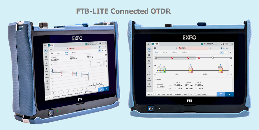
OTDRs driving unmatched field efficiency with always-on connectivity on a rugged platform

D Series OTDR line with Swap-out Connector

AXS-120 - Last-mile/Access mini-OTDR

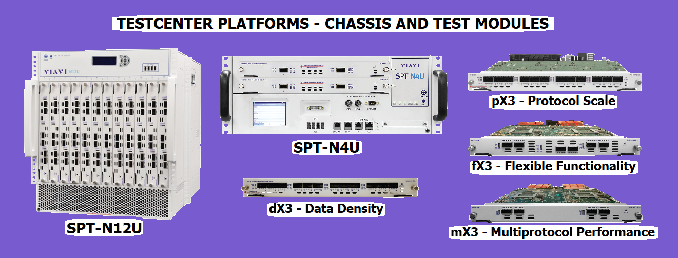
VIAVI TESTCENTER Platforms- Chassis and Test Modules

Fitel S179+ Fusion Splicer and Fitel S327 High Precision Optical Fiber Cleaver
FASTER, MORE RELIABLE FIBER-TO-THE-HOME (FTTH) DEPLOYMENTS
EXFO provides network operations with the expert testing knowledge, tools and environment they need to bridge the OPEX gap created by the increased bandwidth demand. With field-proven methodes and procedures, smart and integrated test solutions and cloud-based data management, FTTH networks can now be deployed reliability and cost-effectively.
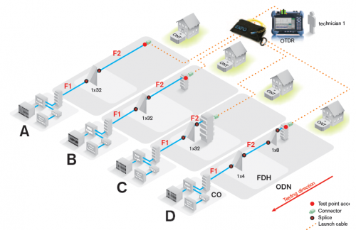
Figure 1 General FTTH Architecture
Figure 1 illustrates the general architecture of a typical FTTH network. At the CO (also referred to as the headend), the public-switched telephone network (PSTN) and Internet services are interfaced with the optical distribution network (ODN) via the optical line terminal (OLT). The downstream 1490 nm and upstream 1310 nm wavelengths are used to transmit data and voice. Analog RF video services are converted to optical format at the 1550 nm wavelength by the optical video transmitter. The 1550 nm and 1490 nm wavelengths are combined by the WDM coupler and transmitted downstream together. IPTV is now transmitted over 1490 nm.
Passive optical distribution network (ODN) equipment consists of gear and components located between the OLT (active) and the customer premises (the ONT; active); this includes both optical and non-optical components of the network. The optical components make up the optical distribution network (ODN) and include splices (fusion and mechanical), connectors, splitters, WDM couplers, fiber-optic cables, patchcords and possibly drop terminals with drop cables. The non-optical components include pedestals, cabinets, patch panels, splice enclosures and miscellaneous hardware.
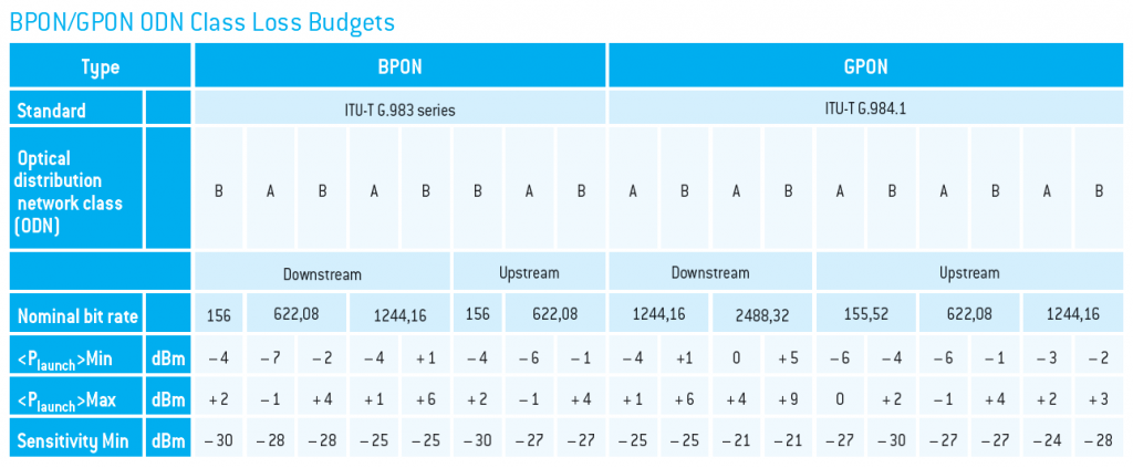
One of the most important factors in ensuring proper transmission is controlling the power losses in the network against the link’s loss-budget specifications from the ITU-T recommendation and standard, which is done by establishing a total end-to-end loss budget with enough of a buffer, while reducing backreflections to a minimum. To adequately characterize the loss budget, the following key parameters are generally considered:
- Transmitter: launch power, temperature and aging
- Fiber connections: splitter, connectors and splices
- Cable: fiber loss and temperature effects
- Receiver: detector sensitivity
- Others: safety margin and repairs
[su_spacer]
Testing Procedure
Once the design of the network has been completed, the lifecycle of a network generally consists of three main phases: construction, activation and maintenance.
1.Construction Phase

As shown in the Table, proper connector care and fiber handling are an important piece of the puzzle to make a network less problem-prone. Another critical aspect is end-to-end fiber mapping/documentation, as this ensures that once the network is up and running, any service interruptions due to network-related issues are resolved in the shortest possible time.
EXFO Solution
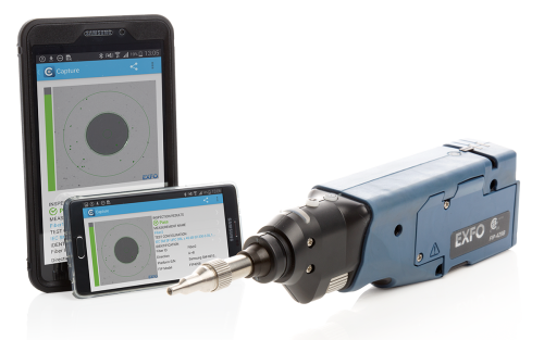
- Fiber Inspection

What To Look
EXFO’s FIP-400B Fully Automated and Intelligent fiber inspection solutions are designed to speed up and simplify this critical step to any fiber testing and help you deploy faster, more reliable fiber networks, providing accurate and consistent test results, and preventing the reporting of false-positive results.
KEY FEATURES
- 100% automated, one-step inspection process
- On-board connector endface analysis
- (IEC, IPC or custom standards) including MPO/MTP analysis.
- Pass/fail LED indicator for immediate diagnosis of connector health
- Optimal digital image quality with three levels of magnification[su_spacer]

[su_spacer](For more information about Fiber Inspection, Click here)
[su_spacer]
- Characterizing Insertion Loss and Optical Return Loss
In this step, both loss and fiber attenuation of the ODN elements must be measured to ensure that they meet supplier specifications. There are several testing approaches to characterized the ODN during construction.
– OLTS Approaches
Advanced automated OLTS solutions, such as EXFO’s FTB-3930 coupled with the FOT-930, can allow multiple technicians to access the same unit. As the FTB-3930 can manage up to 10 references, it can be placed in the CO, connected to the link under test. The technicians in the field, equipped with FOT-930s can use the unit at the CO to perform the test. Note that once the referencing is performed, no technician is required to operate the FTB-3930, and all the test results can automatically be saved in this main unit at the CO.

An OTDR identifies and specifically locates individual events in a fiber-optic span, which typically consists of sections of fiber joined by connectors and splices. The reflectometry test is single-ended and is performed by one technician. The unit transmits pulsed light signals along a fiber span in which light-scattering occurs due to discontinuities such as connectors, splices, bends and faults. The OTDR then detects and analyzes the parts of the signals that are returned by Fresnel reflections and Rayleigh backscattering. The OTDR method is extremely accurate, yet can be complex and time-consuming.
Characterized ODN using OTDR Approaches
(For more information about OTDR, Click here)
[su_spacer]
– iOLM Approaches
The most recent test tool for this application is the intelligent optical link mapper (iOLM). This tool uses the same method as the OTDR, but performs the test procedure automatically. It does this by using different pulse widths to fully characterize the various sections of an FTTH network—each section being characterized with the optimal pulse. Then, the iOLM consolidates all this information into a single comprehensive Link View; the operator does not have to manually compare results at different pulses like a traditional OTDR. The iOLM provides the link’s loss and ORL, in addition to identifying all network elements such as splices, splitters and connectors. It also provides the loss and reflectance values of the identified elements. And when a specific element or the link itself gets a “fail” verdict, it offers a diagnosis to help the operator solve the problem. The whole routine takes 30 to 60 seconds, depending on network complexity.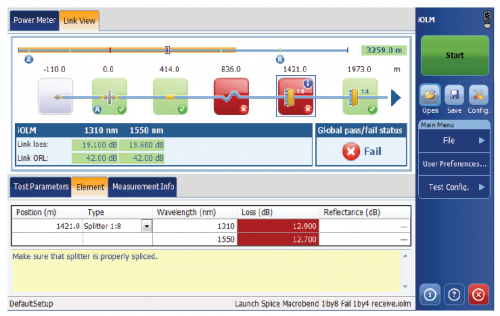
iOLM Test Result
(For more information about iOLM, Click here)
[su_spacer]
2. Service Activation Phase
Service activation is associated with what is known as “home-connect” service turn-up. This process includes the connection between the fiber drop point (FDP) and the optical network terminal (ONT) at the customer’s premises. It is therefore critical that accurate, PON-specific power meters with good track records are used for measurement and documentation purposes.

[su_spacer]
3. Maintenance Phase
When service is activated on a passive optical network (PON), telephony, high-speed Internet and video signals are sent from the optical line terminal (OLT) at the central office (CO) to various optical network terminals (ONTs) at different residential customer locations. In this situation, if one of the ONTs goes down and cannot restart its synchronization with the OLT, this branch of the PON becomes inactive and the customers associated with this branch lose service. The result is that a technician is called in to troubleshoot and restart the service. The faulty zone can be isolated using EXFO PON Power Meter PPM-350C.
Even though a PON power meter can help isolate the affected zone, it cannot provide the exact location of the fault. In order to physically pinpoint the location of a fault, the technician must use what we refer to as a PON-optimized OTDR or iOLM with a dedicated port for testing at 1625 or 1650 nm and incorporate a filter that rejects all unwanted signals (1310, 1490 and 1550 nm) that could contaminate the OTDR-iOLM measurement.
Live Testing with OTDR or iOLM
(For more information about Live testing with OTDR or iOLM, Click here)